Sail Panels for Solar Sail Space Craft with automatic furl and unfurl devices and central Docking and Payload Ring structure

- Đ Frank Ellinghaus -

I N D E X - G E R M A N

POST & AUTHOR & Vision
STS - Solar Thruster Sailor
RSS - Ring Skeleton Structure LTH - Launcher Transport Head EFO - Experimental Flying Object RSC - Rotational Slingshot Catapult
L I N K S ENGLISH

Fig.1 - Fig.2a-2b - Fig.2c - Fig.2d - Fig.3a-3b - Fig.4a-4c - Fig.5 - Fig.6 - Fig.7 - Inner Ring - Flying Ring - Fig.8 - Fig.8a - Fig.8b - Fig.9 - Fig.9a - Fig.10 - Fig.11 - Fig.10 - Fig.11 - Fig.13 - Fig.14-15 - Fig.16 Mobile Thruster Unit - Fig.17 - Fig.18 Fuelless Steering - Fig.19-21d Solar Sail Launch System


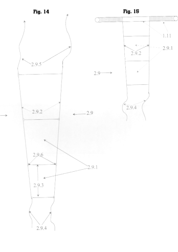
Figures 14 and 15, sail panels

solar sail segment Fig. 14 shows a typical Sail panel 2.9 for automatic roll reefing and setting. It has CNT-threads 2.9.2 at the side-edges to hold the sail above the pipe bodies of the Inner and Outer Rings. There are also rip stops 2.9.3 to prevent tearing.

The Earth weight of such a panel for the authors reference design of about 1111 m, about 4 m width on the long end and about 6 cm width on the small end would be aproximateley between 2.5 kg and 6 kg depending on the thickness of the foil (here between 1.1 to 2.2 micron).

The unfurl winches are pulling the sail toward the sailcraft center with the threads 2.9.4.. To handle the at maximum 6 kg Earth mass of the sail panels under micro gravitation conditions the electric motors for the pulling winches and roll brackets donīt have to develop much force and can be made very lightweight.

Fig. 15 shows a sail panel partly on the roll. The edge-threads 2.9.4 are protecting the sail foil when lying on it. I am pretty sure that such a setup will enable us to get even thinner sail material into space without harming it. To get such a roll into itīs brackets on the Outer Ring is easy compared with folding, launching, unfolding a big folded sail and placing and connecting it to the sail structure.

It will be also easy to repair such a single panel. Just get the panel roll out of their brackets and put another one back.

For a 2260-m diameter sail design with a 30-m docking and payload station the length of one panel would be about 1111 m. Given a foil thnickness of 2.1125 micron (two micron substrat plus two sides aluminum coating) a roll of 6 cm diameter would have a diameter of 6 cm on the sides and of about 8 cm in the middle. With a substrat thickness of 1 micron the middle diameter would only be about 7cm.


to the next ( Fig. 17 )

Fig.1 - Fig.2a-2b - Fig.2c - Fig.2d - Fig.3a-3b - Fig.4a-4c - Fig.5 - Fig.6 - Fig.7 - Inner Ring - Flying Ring - Fig.8 - Fig.8a - Fig.8b - Fig.9 - Fig.9a - Fig.10 - Fig.11 - Fig.10 - Fig.11 - Fig.13 - Fig.14-15 - Fig.16 Mobile Thruster Unit - Fig.17 - Fig.18 Fuelless Steering - Fig.19-21d Solar Sail Launch System


I N D E X - G E R M A N

POST & AUTHOR & Vision
STS - Solar Thruster Sailor
RSS - Ring Skeleton Structure LTH - Launcher Transport Head EFO - Experimental Flying Object RSC - Rotational Slingshot Catapult
L I N K S ENGLISH